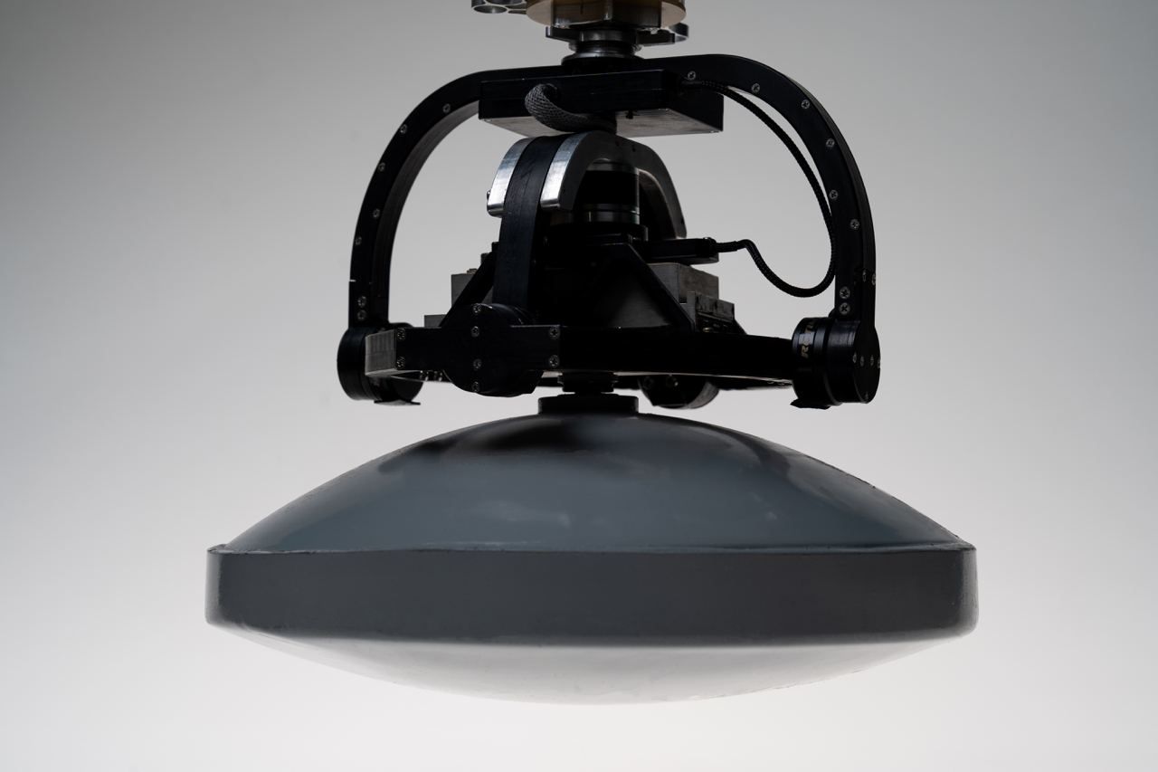
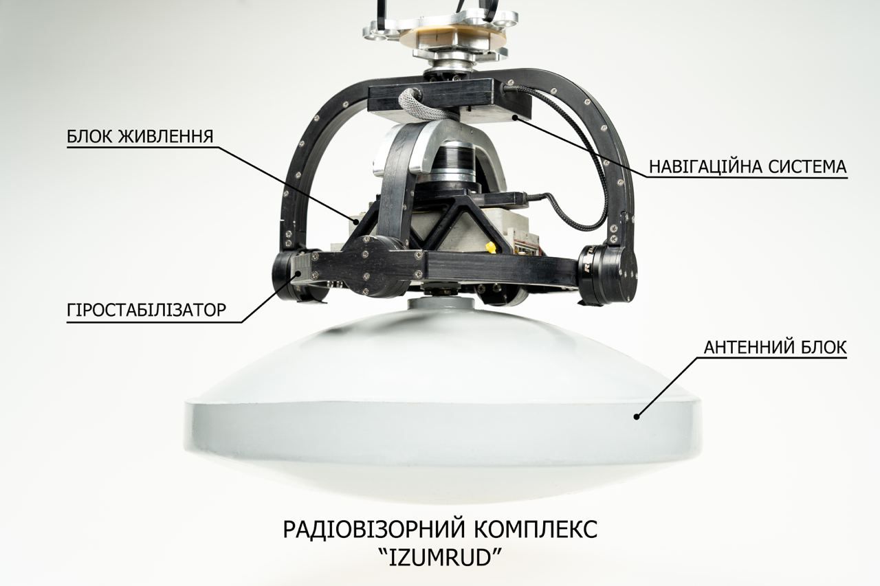
Radiogoniometric Complex "Izumrud"
Radioscope - a device (instrument) for detecting objects and communications, valuable minerals, archaeological treasures, as well as technogenic and natural heterogeneities beneath the Earth's surface or through obstacles.
The main advantages of the 'Izumrud' complex over competing solutions are:
-
Unlike ground-penetrating radar systems that require movement directly on the Earth's surface, the 'Izumrud' complex is a more mobile, versatile, and efficient means of geosurveillance.
-
The main distinction from space systems lies in lower cost and reduced operational expenses.
-
A success rate of 90% or higher in the search for freshwater deposits.
-
Large search research areas covered in a short period.
-
The capability to conduct research in hard-to-reach and inaccessible areas on land and in water.
-
The ability to provide a rapid forecast of water volume prior to obtaining a license.
-
The capability to design the locations for the initial exploration wells.
-
One of the most effective elements of the technology is the use of radio-thermal imaging. The synthesis of infrared thermal and radio-thermal materials enables probing the Earth's depth, from the surface down to the mantle.
-
Unlike thermal imaging systems such as Flir and NEC, which utilize the infrared spectrum, the 'Izumrud' complex operates in the radio frequency range.
By employing the innovative technology of remote sensing of the Earth with the Radiogoniometric Complex 'Izumrud,' it is possible to conduct geological and geophysical mapping with the construction of a volumetric thermodynamic model, identifying:
-
fault zones and fracturing with ranking, permeability zones;
-
zones of stable blocks in the Earth's crust;
-
zones of landslides and mudflows;
-
zones of dangerous geological anomalies during the design, construction, and operation of technologically hazardous facilities (nuclear power plants, thermal power plants, oil and gas storage facilities, loading and unloading terminals, ports, airports, and other construction projects, including hydraulic structures);
-
Mapping of roads and railways, power transmission lines, oil and gas pipelines, tunnels, with their correlation to active fault zones.
And also any structural heterogeneities beneath the Earth's surface and water.
User Manual
RD-16-01 (hereinafter referred to as the radiometer or RD-16-01) includes its description, technical specifications, and other information necessary for consumers to fully utilize its technical capabilities, as well as guidelines for its proper and safe operation.
In terms of resistance to climatic influences, the radiometer belongs to the climatic performance U, placement category 1 according to GOST 15150.
The necessary illustrations are provided in the appendices, with references to them included in the text of the technical documentation.
The electrical diagram of the radiometer and a photo of its external appearance are presented in the appendices.
1. Description and Operation
1.1 Purpose of the Product
1.1.1 The radiometer is designed to measure the radiation temperatures of the Earth's surface. It can be used to monitor temperature contrasts on the Earth's surface or, for example, to create maps of the distribution of radiation temperatures on the Earth's surface.
1.1.2 Operating conditions under arbitrary atmospheric pressure: - ambient temperature: from minus 40 to +55 °C; - relative humidity: up to 100% at a temperature of 25 °C.
1.1.3 Environmental conditions during computer adjustment of the radiometer in the preparation process for operation: - ambient temperature: from +10 to +35 °C; - relative humidity: not more than 80% at a temperature of +25 °C.
1.2 The primary parameters and characteristics of the radiometer.
1.2.1 The operating frequency range is from 26 GHz to 37.5 GHz.
1.2.2 Modulation frequency ranges from 4 to 512 Hz (customizable by the customer).
1.2.3 Continuous operation time, hours, not less than 8.
1.2.4 Power consumption, VA, not exceeding -
1.2.5 Power supply - from a rechargeable battery (depending on the discharge level) – from 20V to 27V.
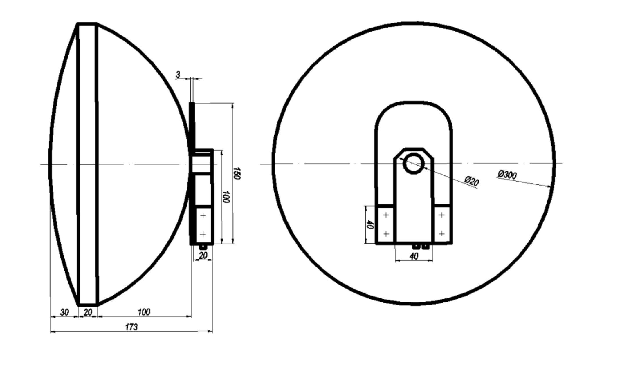
1.2.6 Overall dimensions, mm, not exceeding: - length 300 - width 300 - height 100
1.2.7 Weight, kg, not exceeding – 1.2.
1.2 The main parameters and characteristics of the radiometer 1.2.1 Operating frequency range - from 26 GHz to 37.5 GHz.
1.2.2 Modulation frequency ranges from 4 to 512 Hz (customizable by the customer).
1.2.3 Continuous operation time, hours, not less than 8.
1.2.4 1.2.5 Power consumption, VA, not exceeding - Power supply from a rechargeable battery (depending on the discharge level) – from 20V to 27V.
1.2.6 Overall dimensions, mm, not exceeding:
- length 300
- width 300
- height 100
1.2.7 Weight, kg, not exceeding – 1.2.
1.3 Product Composition:
- Dual-channel radiometer RD-16-01;
- Operation Manual.
1.4 Device and Operation
The dual-channel radiometer RD-16-01 is designed based on the modulation scheme. The electrical diagram of the radiometer is provided in Appendix A.
The parabolic antenna WA1, with a waveguide output, is connected to the standard waveguide with a cross-section of 7.2x3.4 mm, the input hermetic feedthrough of the radiometer housing. The modulation-amplifier microwave path is implemented in a microstrip configuration.
The schematic diagram of the microwave modulator SA1 is based on a PIN diode of the MA4AGSW1A type, manufactured by M/A-COM Technology. It provides sequential connection to the input of the amplifier - the output of the WA1 antenna or the matched load WU1. It differs from others in the small magnitude of the reflected signal. The modulator is controlled by square wave pulses supplied from the control controller A10 and generated on the modulator board A1.
Two cascades, A3 and A4, of low-noise amplification in the frequency range from 26 GHz to 37.5 GHz are implemented using Agilent's AMMC-6241 microchips. At the output, they are matched with the microwave divider XW3 using passive elements WU2.
The mentioned divider XW3, along with passive elements WU2 – WU4, implements the power division of the output signal of low-noise amplifiers into two, and also provides matching with the inputs of amplifiers of the two channels A6 and A7: 26 - 32 GHz in the first channel (input A6) and 32 – 37.5 GHz in the second channel (input A7).
Further amplification of signals in both channels is carried out by amplifiers A6 and A7, also implemented on AMMC-6241 microchips.
The frequency bands in both channels are determined by the bandpass filters ZQ1 and ZQ2: the first channel 26 - 32 GHz; the second channel 32 – 37.5 GHz. The outputs of the filters are matched with the next amplification stages using passive elements WU5 and WU6.
The final microwave amplification stages in both channels, A8 and A9, are implemented on microchips with adjustable gain coefficients.
The СНА2097a from UMS is used in these stages. The gain coefficients are adjusted by changing the bias voltage values of these amplifiers using adjusting elements located on the power board A5.
To reduce the penetration of parasitic signals into the microwave path, all power voltages for the microwave amplifiers (A3, A4, A6-A9) are supplied from the power board A5 through power filters.
The quadratic detectors of both channels are matched at the input with the outputs of amplifiers A8 and A9 in the frequency range of 26 - 32 GHz in the first channel and 32 - 37.5 GHz in the second channel. The detectors are implemented using Agilent diodes.
After the quadratic detectors, the radiometric signals of each channel are amplified by two sequentially connected direct current amplifiers (DCA) A11 - A14. The DCA frequency band is 250 kHz. The output signals have a maximum level of 2 V and are fed to the control controller A10.
All power voltages for the components of the radiometer are supplied from voltage stabilizers located on the DC/DC A2 and power A5 boards.
1.4.1 The structure and operation of the control controller.
The control controller A10 is designed to operate as part of the dual-channel radiometer RD-16-01 and performs the following functions:
- takes radiation temperature measurements and performs the necessary calculations;
- is receiving information from the GPS receiver;
- provides control of the modulator;
- provides control and monitoring from a computer via the USB connection interface;
- provides output of radiometric and GPS receiver information for recording to a file on the SD CARD;
- provides transferring information from SD CARD to computer via USB connection interface.
1.4.1.1 Basic principles of operation of the control controller.
The control controller is based on Silabs C8051F340, C8051F120, C8051F061 microcontrollers. The software is stored in the internal FLASH-memory of the main and subordinate microcontrollers. Information exchange between microcontrollers is performed via UART, SPI interfaces.
The algorithm of the C8051F340 microcontroller is as follows:
- scanning the GPS receiver information;
- analysis of scanning equipment synchronization signals;
- Receiving and analyzing a packet of radiometric information from the C8051F120 microcontroller;
- generation of the statistics file and recording it on the SD CARD:
- receiving, analyzing and executing commands from the computer.
The algorithm of the C8051F120 microcontroller is as follows:
- scanning and MS-DOS executing such commands from the computer;
- analysis of scanning hardware synchronization signals;
- requesting and receiving packets with radiometric information from C8051F061 microcontrollers;
- carrying out calculations and transferring the radiometric information package to the C8051F340 microcontroller.
The algorithm of the C8051F061 microcontroller is as follows:
- scanning control signals from the C8051F120 microcontroller;
- control of the radiometric channel modulator;
- voltage measurement (radiation temperature equivalent) using an analog-to-digital converter and making the necessary calculations;
- transmission of radiometric information packet on request from C8051F120 microcontroller
1.4.2 Radiometer design
All radio-electronic elements and assemblies of the radiometer are placed in a sealed case. Refer to Appendix B for an external view of the radiometer.
The sealed connector XP2 of the RSG-10 radiometer is designed for supplying power voltage, control signals and connection of the GPS device. See the radiometer schematic in Appendix A. The RSG-10 pins of the radiometer are supplied with:
1,2 - signals controlling the start and end of the scanning cycle (SCAN)
3,4 - scan cycle synchronization signals (2PS)
5,6,7,8 - power and signals information communication with the GPS device;
9,10 - adiometer power supply from the battery - 20 ... 27 В.
The construction of the radiometer has a removable hermetic cover, the opening of which allows you to connect to the radiometer computer, which is used to configure and capture information.
2. Intended use
2.1 Operational limitations
2.1.1 The radiometer may not be operated under conditions beyond the limits specified in p. 1.1.2 and p. 1.1.3 of this manual. 1.1.2 and 1.1.3 of this manual.
2.2 Radiometer use
2.2.1 Controls and indications
The following controls and indications are located on the control controller board:
Connector "USB_CONTROL" - is used to control and check the radiometer equipment with the help of computer software.
Connector "USB_MSD_RD" - is used for reading statistic files using computer software. SD_CARD" connector - is used to connect a memory card to which statistics files are recorded by the control controller.
2.2.2 Control commands from the computer.
Computer control commands are similar to those of the MS-DOS operating system. You can enter such commands using an application-specific program or the Windows operating system communication program, Hyper Terminal:
1 The "rst" command performs a program restart of the control controller.
2 The setnstep command sets the number of steps in one scan in the range of 1; 2; 4; 4, 8; 16; 32; 32; 64; 64; 128; 256 (for example - setnstep 64).
3 The getnstep command allows you to check the value of the number of steps in one scan.
4 The "mrk" command allows checking the results of radiation temperature (equivalent voltage) measurement at the output of the radiometer receivers.
5 The "gps" command allows you to check the initial data of the satellite navigation system receiver.
6 The "rstname" command lists the name of the statistics file as "00000000".
2.2.3 Procedure for preparing the radiometer for operation.
2.2.3.1 Unscrew the screws securing the sealed cover and remove it (to provide access to the controls of the radio-meter control controller).
2.2.3.2 Supply power to the radiometer, namely - connect power supply from the 27 V battery (connection method - in accordance with the power supply scheme at the level meter user's site).
2.2.3.3 Connect the computer with a standard cable to the "USB_CONTROL" input and start the operating system program "Windows - Hyper Terminal".
2.2.3.4 Perform sequentially the control commands - p.p. 1-5 according to p.2.2.2 of this manual. 1-5 according to paragraph 2.2.2 of this manual.
2.2.3.5 Close the "Hyper Terminal" program and disconnect the computer from the "USB_CONTROL" input.
2.2.3.6 Turn off the power to the radiometer.
2.2.3.7 Close the sealed cover of the radiometer.
2.2.3.8 Radiometer RD-16-01 is ready for scanning of the earth surface with automatic recording of information in the memory of the control controller; it is only necessary to supply power supply in accordance with clause 2.2.3.2, as well as to supply scanning control signals: 2PPS and SSAN of amplitude level TTL.
2.2.4 Procedure for reading the working files of the radiometer statistics.
2.2.4.1 Remove the sealing cover in the same way as in section 2.2.3.1.
2.2.4.2 Supply power to the radiometer, similar to paragraph 2.2.3.2.
2.2.4.3 Connect the computer with a standard cable to the USB_MSD_RD input. In this case it is possible to overwrite statistic files using standard methods of Windows operating system.
2.2.4.4 Disconnect the computer from the USB_ MSD_RD input.
2.2.4.5 Turn off the radiometer's power supply.
2.2.4.6To replace the memory card to which the statistics files were written by the control controller or to use the memory card as part of the data processing computer, you must remove the memory card from the SD_CARD slot of the control controller and insert it into the corresponding slot of the computer.
2.2.4.7 After completion of all manipulations with the radiometer it is necessary to close the sealed cover of the radiometer and clamp the corresponding screws of its fixing.
2.3 Actions under extreme conditions.
2.3.1 The radiometer requires no adjustments during scanning and can operate continuously for up to 8 hours.
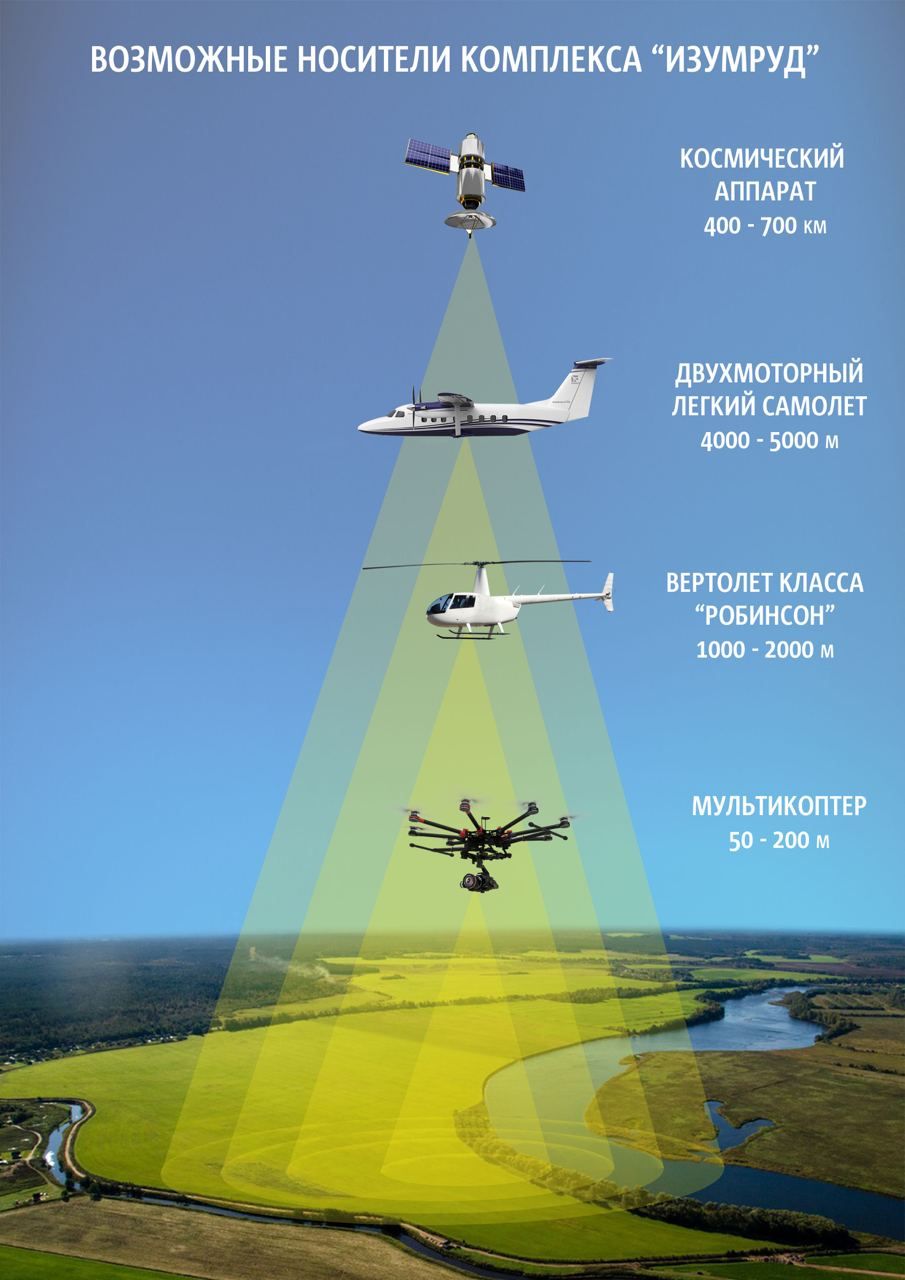
Description of "IZUMRUD" complex carriers
The Izumrud complex has a three-axis electronic gyrostabilization system, an antenna swing system, and a carrier mount assembly.
The carrier of the "IZUMRUD" complex may include:
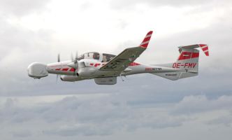
1. Airplane of the 4th class
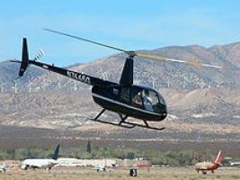
2. "Robinson" helicopter.
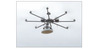
3. Unmanned multicopter
The unmanned system is a radio-controlled, eight-motor drone equipped with a radiometer on a controlled gyro-stabilized platform.
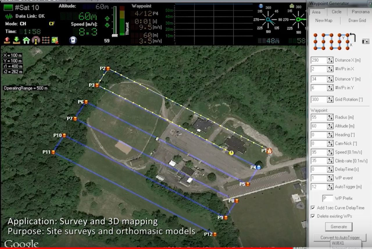
The drone works according to a predetermined trajectory that is loaded by the operator before the flight.
The drone is equipped with a directional camera that allows you to control the flight visually. GPS coordinates for the payload are read from an external GPS moduleThe complex is designed to operate in rain, fog and precipitation, and is protected from moisture and rain, which allows safe landing in case of sudden weather changes. The complex is designed for automobile basing in a cargo-passenger minibus and is placed in four cases.
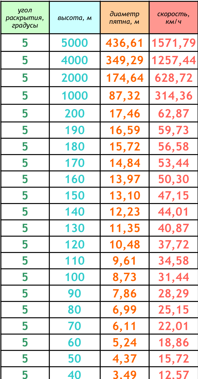
For different types of carriers of the radio-imaging complex "Izumrud" optimal parameters of operation, altitudes, speeds and coverage of working territories were calculated.

Contacts
"Center of Aerospace Technologies" Ltd
Bulgaria, 8000
Burgas, Antim I, str. 26
Tel:
-
+359 89 462 0030
-
+380 67 632 9101
e-mail:
-
This email address is being protected from spambots. You need JavaScript enabled to view it. -
This email address is being protected from spambots. You need JavaScript enabled to view it.

